Specifications
Assembly
Tutorial
Component
Feedback
Product Description
- Used for coupling spatial laser beams into fiber optic patch cords
- Compatible with various models of aspheric lenses and collimating devices
- Compatible with 30 mm coaxial systems and free-space optical paths
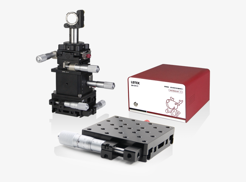
The LBTEK fiber coupling system mainly consists of three parts: coarse adjustment, matching, and coupling:
(1) Coarse adjustment part: Coarsely adjusts the pitch and yaw angles of the incident light to ensure parallel incidence;
(2) Matching part: The XY-direction displacement adjustment stage and the Z-axis translation mount are equipped with lens groups for fine-tuning the design beam waist of the fiber collimator. Lenses with appropriate focal lengths can be selected based on experimental requirements (LBTEK offers various lenses, such as aspheric lenses, achromatic cemented lenses, etc.);
(3) Coupling part: Used to fix the fiber collimator and connect the fiber jumper.
Contact LBTEK technical support for more system details and product selection.
Attribute
Material6061-T6 aluminum alloy, 304 stainless steel
Applicable optical element diameter25.4 mm
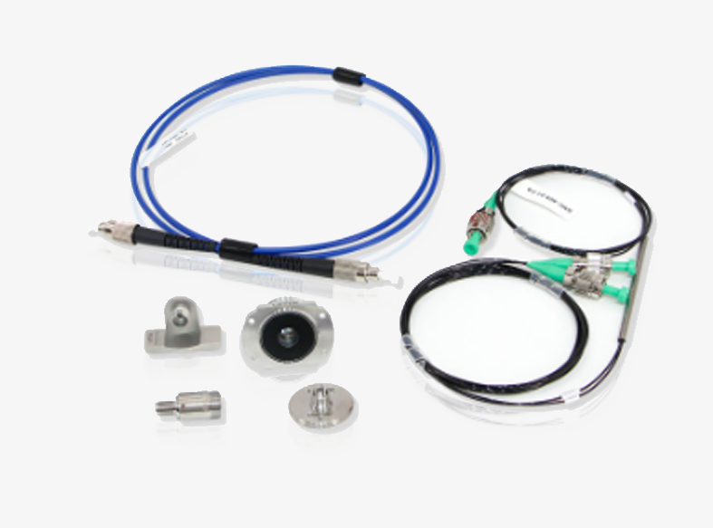
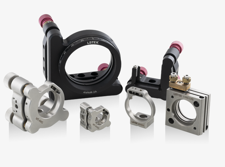
Fiber Optic Coupling System Mechanical Components
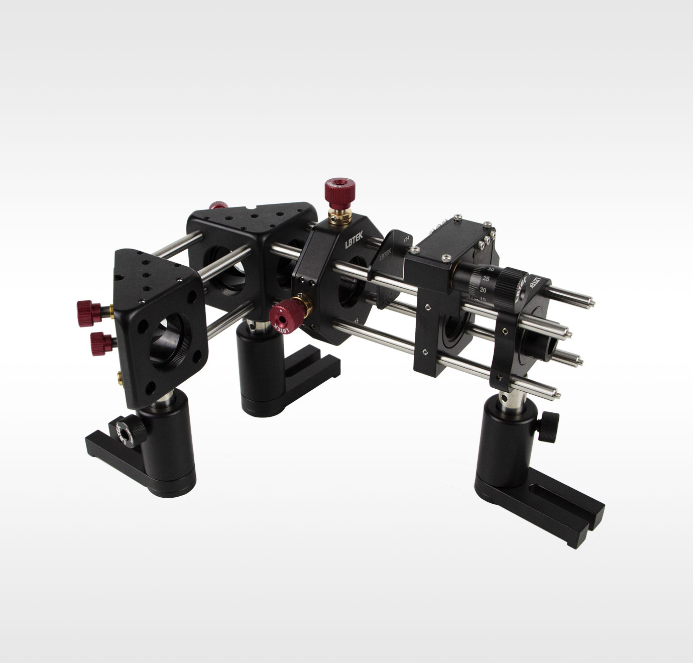
- Precision micrometer drives provide micron-level translation
- Simultaneously satisfying five-dimensional adjustments in XYZ and θX, θY
- Compatible with 30 mm coaxial systems and free-space optical paths
The simple fiber coupling system provided by LBTEK is used for manually coupling spatial laser beams into fiber optic patch cords. In addition to the basic mechanical components, it includes a 30 mm coaxial system alignment plate CT-1, ensuring the collimation of incident light while keeping the beam centered on the optical components as much as possible. Furthermore, the fiber optic patch cord interface type depends on the fiber collimator selected by the user (which needs to be purchased separately by the user). First, observe whether the beam is precisely centered on the fiber collimator, then confirm whether the output spot shape is circular. If both conditions are met, insert the fiber and monitor at the fiber output end. Adjust the two mirror mounts in the collimation section and the MFT to achieve higher coupling efficiency.
Note: Only mechanical components are included; optical components need to be purchased separately. For purchasing details, please refer to the technical specifications.
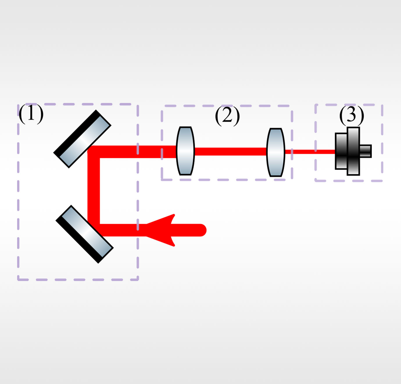
Basic optical path of fiber coupling system
Product Model | Applicable optical element diameter | Unit Price | Compare | Lead Time | ||
|---|---|---|---|---|---|---|
| SLCS-V1 | 25.4 mm | $692.54 | 1week |
Address:Building A6, Huanchuang Enterprise Plaza, Yuelu Idstrict, Changsha
Email: service@lbtek.com、sales@lbtek.com
Tel: 400-060-6986 (Mon-Sun 9:00-18:00)
 WeChat
 TikTok
 Zhihu
Zhihu Bilibili