%20--%3e%3csvg%20version='1.1'%20id='图层_1'%20xmlns='http://www.w3.org/2000/svg'%20xmlns:xlink='http://www.w3.org/1999/xlink'%20x='0px'%20y='0px'%20viewBox='0%200%20289.2%2071.5'%20style='enable-background:new%200%200%20289.2%2071.5;'%20xml:space='preserve'%3e%3cstyle%20type='text/css'%3e%20.st0{fill-rule:evenodd;clip-rule:evenodd;fill:%23B81C22;}%20.st1{fill:%23B81C22;}%20%3c/style%3e%3cg%3e%3cpath%20class='st0'%20d='M286.5,2.7c-0.2-0.5-0.7-1-1.6-1c-4.1,0-9.1,0-9.1,0c-2.9,0-6.1,3.1-6.1,3.1c0,0-13,14.6-21.8,23.4l-1,1%20l2.3-18.7c0.3-2.2-0.4-4.5-1.9-6.1c-1.5-1.7-3.6-2.7-5.9-2.7h-2.8c-1,0-1.8,0.7-1.9,1.7l-8.3,65.1c-0.1,0.5,0.1,1.1,0.5,1.5%20c0.4,0.4,0.9,0.7,1.4,0.7h3c4.8,0,8.8-3.5,9.4-8.3l1.8-14.2l6.6-6.6l0.3,0.5c3.5,5.3,16.2,24.4,16.9,25.6c0.4,0.4,1.9,3.1,6.2,3.1%20l8.6-0.1c0.8,0,1.4-0.4,1.7-1.1c0.3-0.7,0.3-1.4-0.1-2.1l-22.1-32.5c-1.2-1.7-1-4,0.5-5.5l23.1-24.8C286.7,3.9,286.7,3.2,286.5,2.7%20'/%3e%3cpath%20class='st0'%20d='M174.4,14.3C174.4,14.3,174.4,14.2,174.4,14.3L176,4c0.1-0.7-0.1-1.3-0.5-1.8c-0.4-0.5-1.1-0.8-1.8-0.8h-50.4%20c-1.5,0-3,1.2-3.2,2.7l-1.3,10.2h21.1l-7.1,56.2l13.1,0c0.1,0,0.1-0.1,0.1-0.1l7.4-56.2H174.4z'/%3e%3cpath%20class='st0'%20d='M13,1.4h-2.6c-0.9,0-1.8,0.8-1.9,1.7L0.8,64.4c-0.2,1.6,0.2,3,1.2,4.1c1,1.1,2.5,1.8,4.1,1.8h39.7%20c1.3,0,2.4-1,2.6-2.3c0.4-3-0.4-5.8-2.3-7.9c-1.9-2.1-4.6-3.3-7.6-3.3H23.7c-1.6,0-3.1-0.7-4.1-1.9c-1.1-1.2-1.5-2.8-1.3-4.3%20L23,12.7c0.4-3-0.4-5.8-2.3-8C18.8,2.6,16.1,1.4,13,1.4'/%3e%3cpath%20class='st0'%20d='M223,40.3c0.3,0,0.5-0.2,0.6-0.5l1.1-8.4c0-0.1,0-0.2-0.1-0.3c-0.1-0.1-0.1-0.1-0.3-0.1h-8%20c-0.3,0-0.5,0.2-0.6,0.5l-1.1,8.4c0,0.1,0,0.2,0.1,0.3c0.1,0.1,0.1,0.1,0.3,0.1H223z'/%3e%3cpath%20class='st0'%20d='M229,1.4h-35.4c-6.9,0-13.1,5.5-14,12.3L174,58c-0.4,3.3,0.5,6.4,2.6,8.7c2,2.3,4.9,3.6,8.2,3.6h35.8l0.5-5%20c0.2-2.1-0.5-4.1-1.9-5.7c-1.4-1.5-3.4-2.4-5.5-2.4l-17.2,0c-2.2,0-4.2-0.9-5.6-2.5c-1.4-1.6-2-3.7-1.8-6c0.6-4.5,4.7-8.3,9.3-8.3%20l11.5,0c0.3,0,0.6-0.2,0.6-0.5l1-8.3c0-0.1,0-0.2-0.1-0.3c-0.1-0.1-0.2-0.1-0.3-0.1l-11.6,0h0c-3.2,0-5.5-1.3-6.6-3.6%20c-1.3-2.8-1.1-6,0.6-8.6c1.8-2.8,4.8-4.5,8-4.5h18.1c4.5,0,8.3-3.3,8.8-7.8L229,1.4z'/%3e%3cpath%20class='st1'%20d='M112.3,9.9c-1.5-2.9-3.8-5.1-7-6.5c-3.1-1.4-7.4-2.1-12.8-2.1l-25.4,0h0c-2.5,0-4.8,2-5.1,4.5l-7.3,57.9%20c-0.2,1.8,0.3,3.4,1.4,4.7c1.1,1.3,2.7,1.9,4.5,1.9h23.5c4.5,0,8.4-0.4,11.6-1.2c3.2-0.8,6-1.9,8.3-3.5c2.3-1.5,4.4-3.8,6.2-6.6%20c1.8-2.8,2.9-5.9,3.3-9.1c0.5-4.1-0.2-7.6-2.2-10.6c-1.6-2.4-3.9-4.3-7-5.6l-0.9-0.4l0.9-0.5c2.5-1.4,4.6-3.2,6.1-5.3%20c2-2.7,3.2-5.5,3.6-8.5C114.4,15.9,113.8,12.8,112.3,9.9%20M101.5,21.7c-0.5,4-4,7.1-7.9,7.2H78.4l-0.2,1.3c-0.3,2.7,0.4,5.2,2.1,7.1%20c1.7,1.9,4.1,2.9,6.8,2.9h3.4c0.6,0,1.2,0.1,1.7,0.2c0.3,0,0.6,0.1,0.8,0.2l0,0.5l0.1-0.5c3.5,1.1,5.5,4.4,5.1,8.2%20c-0.6,4.6-4.8,8.4-9.5,8.4H71.4c-0.6,0-1.2-0.3-1.6-0.7c-0.4-0.5-0.6-1-0.5-1.6l4.9-38.6c0.1-1.1,1-1.8,2.1-1.8h0%20c15.3,0,18.2,0,18.8,0l0,0c1.9,0,3.7,0.8,4.9,2.1C101.2,17.9,101.7,19.7,101.5,21.7'/%3e%3c/g%3e%3c/svg%3e)
- Precision Control of Delay Time by Altering the Light’s Transmission Distance
- Low Insertion Loss, Multi-Stage Delay, Picosecond-Level Resolution
- Single-Mode Fiber, FC/APC Connectors

- Operating Wavelength: 1550 nm
- Manually Adjustable Delay Range: 100 mm
- Low Insertion Loss, High Return Loss
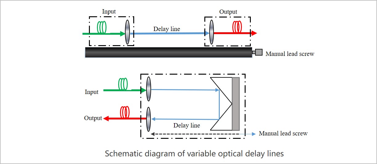
The LBTEK Manual Adjustable Optical Delay Line (Single Pass) is a device that precisely controls the delay time by altering the length of the delay path between the input and output optical ports. It uses air as the optical transmission delay medium, and the delay distance between the input and output optical ports is manually adjusted via a motion mechanism (i.e., a lead screw guide rail). The device features input and output ports each equipped with a 1 m single-mode fiber pigtail and FC/APC connectors. The manual adjustment range of the lead screw guide rail is 100 mm.

LBTEK Manual Adjustable Optical Delay Line (Single Pass)
Product Model | Operating Wavelength | Travel range | Delay range | Unit Price | Compare | Lead Time | ||
|---|---|---|---|---|---|---|---|---|
 | LBODL-100 | 1550 nm | 100 mm | 330 ps | Contact | Contact | Add Cart |

- Operating Wavelength: 1550 nm
- Manually Adjustable Delay Range: 50 mm
- Low Insertion Loss, High Return Loss
The LBTEK manual adjustable optical delay line (double-pass) is a device that precisely controls the delay time by altering the length of the delay path of the movable mirror. It uses air as the optical transmission delay medium, and the delay displacement of the movable mirror is manually adjusted via a motion mechanism (i.e., a lead screw guide rail). The device features input and output ports each equipped with a 1 m single-mode fiber pigtail and FC/APC connectors. The manual adjustment range of the lead screw guide rail is 25 mm, providing a delay range of 50 mm.

LBTEK Manual Adjustable Optical Delay Line (Double Pass)
Product Model | Operating Wavelength | Travel range | Delay range | Unit Price | Compare | Lead Time | ||
|---|---|---|---|---|---|---|---|---|
| LBODL-600 | 1550 nm | 25×2=50 mm | 167 ps | Contact | Contact | Add Cart |
Email: support@lbtek.com
Tel: 400-060-6986 (Mon-Sun 9:00-18:00)
 WeChat
 TikTok
 Zhihu
Zhihu Bilibili