%20--%3e%3csvg%20version='1.1'%20id='图层_1'%20xmlns='http://www.w3.org/2000/svg'%20xmlns:xlink='http://www.w3.org/1999/xlink'%20x='0px'%20y='0px'%20viewBox='0%200%20289.2%2071.5'%20style='enable-background:new%200%200%20289.2%2071.5;'%20xml:space='preserve'%3e%3cstyle%20type='text/css'%3e%20.st0{fill-rule:evenodd;clip-rule:evenodd;fill:%23B81C22;}%20.st1{fill:%23B81C22;}%20%3c/style%3e%3cg%3e%3cpath%20class='st0'%20d='M286.5,2.7c-0.2-0.5-0.7-1-1.6-1c-4.1,0-9.1,0-9.1,0c-2.9,0-6.1,3.1-6.1,3.1c0,0-13,14.6-21.8,23.4l-1,1%20l2.3-18.7c0.3-2.2-0.4-4.5-1.9-6.1c-1.5-1.7-3.6-2.7-5.9-2.7h-2.8c-1,0-1.8,0.7-1.9,1.7l-8.3,65.1c-0.1,0.5,0.1,1.1,0.5,1.5%20c0.4,0.4,0.9,0.7,1.4,0.7h3c4.8,0,8.8-3.5,9.4-8.3l1.8-14.2l6.6-6.6l0.3,0.5c3.5,5.3,16.2,24.4,16.9,25.6c0.4,0.4,1.9,3.1,6.2,3.1%20l8.6-0.1c0.8,0,1.4-0.4,1.7-1.1c0.3-0.7,0.3-1.4-0.1-2.1l-22.1-32.5c-1.2-1.7-1-4,0.5-5.5l23.1-24.8C286.7,3.9,286.7,3.2,286.5,2.7%20'/%3e%3cpath%20class='st0'%20d='M174.4,14.3C174.4,14.3,174.4,14.2,174.4,14.3L176,4c0.1-0.7-0.1-1.3-0.5-1.8c-0.4-0.5-1.1-0.8-1.8-0.8h-50.4%20c-1.5,0-3,1.2-3.2,2.7l-1.3,10.2h21.1l-7.1,56.2l13.1,0c0.1,0,0.1-0.1,0.1-0.1l7.4-56.2H174.4z'/%3e%3cpath%20class='st0'%20d='M13,1.4h-2.6c-0.9,0-1.8,0.8-1.9,1.7L0.8,64.4c-0.2,1.6,0.2,3,1.2,4.1c1,1.1,2.5,1.8,4.1,1.8h39.7%20c1.3,0,2.4-1,2.6-2.3c0.4-3-0.4-5.8-2.3-7.9c-1.9-2.1-4.6-3.3-7.6-3.3H23.7c-1.6,0-3.1-0.7-4.1-1.9c-1.1-1.2-1.5-2.8-1.3-4.3%20L23,12.7c0.4-3-0.4-5.8-2.3-8C18.8,2.6,16.1,1.4,13,1.4'/%3e%3cpath%20class='st0'%20d='M223,40.3c0.3,0,0.5-0.2,0.6-0.5l1.1-8.4c0-0.1,0-0.2-0.1-0.3c-0.1-0.1-0.1-0.1-0.3-0.1h-8%20c-0.3,0-0.5,0.2-0.6,0.5l-1.1,8.4c0,0.1,0,0.2,0.1,0.3c0.1,0.1,0.1,0.1,0.3,0.1H223z'/%3e%3cpath%20class='st0'%20d='M229,1.4h-35.4c-6.9,0-13.1,5.5-14,12.3L174,58c-0.4,3.3,0.5,6.4,2.6,8.7c2,2.3,4.9,3.6,8.2,3.6h35.8l0.5-5%20c0.2-2.1-0.5-4.1-1.9-5.7c-1.4-1.5-3.4-2.4-5.5-2.4l-17.2,0c-2.2,0-4.2-0.9-5.6-2.5c-1.4-1.6-2-3.7-1.8-6c0.6-4.5,4.7-8.3,9.3-8.3%20l11.5,0c0.3,0,0.6-0.2,0.6-0.5l1-8.3c0-0.1,0-0.2-0.1-0.3c-0.1-0.1-0.2-0.1-0.3-0.1l-11.6,0h0c-3.2,0-5.5-1.3-6.6-3.6%20c-1.3-2.8-1.1-6,0.6-8.6c1.8-2.8,4.8-4.5,8-4.5h18.1c4.5,0,8.3-3.3,8.8-7.8L229,1.4z'/%3e%3cpath%20class='st1'%20d='M112.3,9.9c-1.5-2.9-3.8-5.1-7-6.5c-3.1-1.4-7.4-2.1-12.8-2.1l-25.4,0h0c-2.5,0-4.8,2-5.1,4.5l-7.3,57.9%20c-0.2,1.8,0.3,3.4,1.4,4.7c1.1,1.3,2.7,1.9,4.5,1.9h23.5c4.5,0,8.4-0.4,11.6-1.2c3.2-0.8,6-1.9,8.3-3.5c2.3-1.5,4.4-3.8,6.2-6.6%20c1.8-2.8,2.9-5.9,3.3-9.1c0.5-4.1-0.2-7.6-2.2-10.6c-1.6-2.4-3.9-4.3-7-5.6l-0.9-0.4l0.9-0.5c2.5-1.4,4.6-3.2,6.1-5.3%20c2-2.7,3.2-5.5,3.6-8.5C114.4,15.9,113.8,12.8,112.3,9.9%20M101.5,21.7c-0.5,4-4,7.1-7.9,7.2H78.4l-0.2,1.3c-0.3,2.7,0.4,5.2,2.1,7.1%20c1.7,1.9,4.1,2.9,6.8,2.9h3.4c0.6,0,1.2,0.1,1.7,0.2c0.3,0,0.6,0.1,0.8,0.2l0,0.5l0.1-0.5c3.5,1.1,5.5,4.4,5.1,8.2%20c-0.6,4.6-4.8,8.4-9.5,8.4H71.4c-0.6,0-1.2-0.3-1.6-0.7c-0.4-0.5-0.6-1-0.5-1.6l4.9-38.6c0.1-1.1,1-1.8,2.1-1.8h0%20c15.3,0,18.2,0,18.8,0l0,0c1.9,0,3.7,0.8,4.9,2.1C101.2,17.9,101.7,19.7,101.5,21.7'/%3e%3c/g%3e%3c/svg%3e)
- Stopband Range: 200 nm-1100 nm, 200 nm-1200 nm
- Stopband OD Value: ≥4
- FWHM=3±0.6 nm, 10±2 nm, 25±3 nm, 50±5 nm
- Center Wavelength: 405-1064 nm
- Outer Diameter 25.4 mm, with mechanical retaining ring
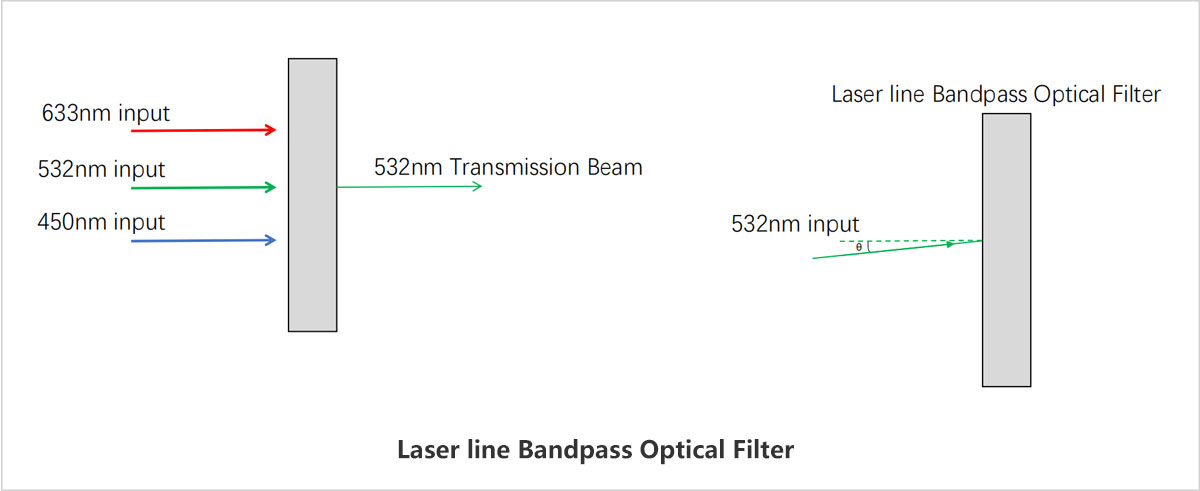

- Center Wavelength: 532 nm
- FWHM: 3±0.6 nm
- Transmittance (@532 nm): >60%
- Stopband Range: 200 nm-1200 nm
LBTEK filters are mounted in black anodized aluminum rings, with the incident direction marked by an arrow on the housing for easy installation and use. In order to prevent the substrate coated with the cutoff material from being subjected to radiation outside the passband wavelength, which may cause thermal effects and reduce the filter characteristics, it is recommended that the side coated with the cutoff film face the light source (light propagates in the direction of the arrow). The filter's dielectric coating thickness is designed based on collimated light incident perpendicularly. If the light is not collimated or incident perpendicularly on the filter surface, the designed center wavelength will shift to a shorter wavelength, and the bandpass transmittance curve will change. All LBTEK circular lenses can be mounted in LBTEK standard lens tubes, fixed lens mounts, and various coaxial mounting plates. Customers can select the optimal mounting method for different application scenarios.

LBTEK coaxial mounting plate can be used to install laser line filters.
Product Model | Center wavelength | Full Width at Half Maximum (FWHM) | Transmittance | Stopband range | Unit Price | Curve | Compare | Lead Time | ||
|---|---|---|---|---|---|---|---|---|---|---|
 | MBF10-532-03 | 532±0.6 nm | 3±0.6 nm | > 60% | 200nm -1200 nm | $153.23 |  | today | Add Cart |

- Center Wavelength: 405 nm-1064 nm
- FWHM: 10±2 nm
- Stopband Range: 200 nm-1100 nm, 200 nm-1200 nm
LBTEK filters are mounted in black anodized aluminum rings, with the incident direction marked by an arrow on the housing for easy installation and use. In order to prevent the substrate coated with the cutoff material from being subjected to radiation outside the passband wavelength, which may cause thermal effects and reduce the filter characteristics, it is recommended that the side coated with the cutoff film face the light source (light propagates in the direction of the arrow). The filter's dielectric coating thickness is designed based on collimated light incident perpendicularly. If the light is not collimated or incident perpendicularly on the filter surface, the designed center wavelength will shift to a shorter wavelength, and the bandpass transmittance curve will change. All LBTEK circular lenses can be mounted in LBTEK standard lens tubes, fixed lens mounts, and various coaxial mounting plates. Customers can select the optimal mounting method for different application scenarios.

Product Model | Center wavelength | Full Width at Half Maximum (FWHM) | Transmittance | Stopband range | Unit Price | Curve | Compare | Lead Time | ||
|---|---|---|---|---|---|---|---|---|---|---|
| MBF10-355-10 | 355±2 nm | 10±2 nm | > 50% | 200nm -1200 nm | $119.50 | | today | Add Cart | |
| MBF10-405-10 | 405±2 nm | 10±2 nm | > 37% | 200nm -1200 nm | $119.50 | | today | Add Cart | |
| MBF10-450-10 | 450±2 nm | 10±2 nm | > 45% | 200nm -1200 nm | $113.48 | | today | Add Cart | |
| MBF10-473-10 Upgrade | 473±2 nm | 10±2 nm | > 90% | 200 nm-1100 nm | $119.50 | | today | Add Cart | |
| MBF10-488-10 | 488±2 nm | 10±2 nm | > 50% | 200nm -1200 nm | $119.50 | | today | Add Cart | |
| MBF10-520-10 | 520±2 nm | 10±2 nm | > 50% | 200nm -1200 nm | $119.50 | | today | Add Cart | |
| MBF10-532-10 | 532±2 nm | 10±2 nm | > 70% | 200nm -1200 nm | $119.50 | | today | Add Cart | |
| MBF10-545-10 Upgrade | 545±2 nm | 10±2 nm | > 90% | 200 nm-1100 nm | $119.50 | | today | Add Cart | |
| MBF10-562-10 Upgrade | 562±2 nm | 10±2 nm | > 90% | 200 nm-1100 nm | $119.50 | | today | Add Cart | |
| MBF10-580-10 Upgrade | 580±2 nm | 10±2 nm | > 90% | 200 nm-1100 nm | $119.50 | | today | Add Cart | |
| MBF10-590-10 Upgrade | 590±2 nm | 10±2 nm | > 90% | 200 nm-1100 nm | $119.50 | | today | Add Cart | |
| MBF10-600-10 Upgrade | 600±2 nm | 10±2 nm | > 90% | 200 nm-1100 nm | $119.50 | | today | Add Cart | |
| MBF10-625-10 Upgrade | 625±2 nm | 10±2 nm | > 90% | 200 nm-1100 nm | $119.50 | | today | Add Cart | |
| MBF10-635-10 | 635±2 nm | 10±2 nm | > 70% | 200nm -1200 nm | $119.50 | | today | Add Cart | |
| MBF10-660-10 Upgrade | 660±2 nm | 10±2 nm | > 90% | 200nm -1200 nm | $119.50 | | today | Add Cart | |
| MBF10-780-10 | 780±2 nm | 10±2 nm | > 50% | 200nm -1200 nm | $119.50 | | today | Add Cart | |
| MBF10-800-10 Upgrade | 800±2 nm | 10±2 nm | > 90% | 200 nm-1100 nm | $119.50 | | today | Add Cart | |
| MBF10-808-10 | 808±2 nm | 10±2 nm | > 50% | 200nm -1200 nm | $119.50 | | today | Add Cart | |
| MBF10-850-10 | 850±2 nm | 10±2 nm | > 50% | 200nm -1200 nm | $119.50 | | today | Add Cart | |
| MBF10-940-10 Upgrade | 940±2 nm | 10±2 nm | > 90% | 200 nm-1100 nm | $119.50 | | today | Add Cart | |
| MBF10-1030-10 | 1030±2 nm | 10±2 nm | > 50% | 200nm -1200 nm | $119.50 | | today | Add Cart | |
| MBF10-1064-10 Upgrade | 1064±2 nm | 10±2 nm | > 90% | 200nm -1200 nm | $119.50 | | 8 weeks | Add Cart |

- Center Wavelength: 400 nm-975 nm
- FWHM: 25±3 nm
- Stopband Range: 200 nm-1100 nm
LBTEK filters are mounted in black anodized aluminum rings, with the incident direction marked by an arrow on the housing for easy installation and use. In order to prevent the substrate coated with the cutoff material from being subjected to radiation outside the passband wavelength, which may cause thermal effects and reduce the filter characteristics, it is recommended that the side coated with the cutoff film face the light source (light propagates in the direction of the arrow). The filter's dielectric coating thickness is designed based on collimated light incident perpendicularly. If the light is not collimated or incident perpendicularly on the filter surface, the designed center wavelength will shift to a shorter wavelength, and the bandpass transmittance curve will change. All LBTEK circular lenses can be mounted in LBTEK standard lens tubes, fixed lens mounts, and various coaxial mounting plates. Customers can select the optimal mounting method for different application scenarios.

LBTEK coaxial mounting plate can be used to install bandpass filters.
Product Model | Center wavelength | Full Width at Half Maximum (FWHM) | Transmittance | Stopband range | Unit Price | Curve | Compare | Lead Time | ||
|---|---|---|---|---|---|---|---|---|---|---|
| MBF10-400-25 | 400±3 nm | 25±3 nm | > 90% | 200 nm-1100 nm | $190.10 | | today | Add Cart | |
| MBF10-450-25 | 450±3 nm | 25±3 nm | > 90% | 200 nm-1100 nm | $190.10 | | 7 weeks | Add Cart | |
| MBF10-550-25 | 550±3 nm | 25±3 nm | > 90% | 200 nm-1100 nm | $190.10 | | today | Add Cart | |
| MBF10-650-25 | 650±3 nm | 25±3 nm | > 90% | 200 nm-1100 nm | $190.10 | | today | Add Cart | |
| MBF10-800-25 | 800±3 nm | 25±3 nm | > 90% | 200 nm-1100 nm | $203.04 | | today | Add Cart | |
| MBF10-850-25 | 850±2 nm | 25±3 nm | > 90% | 200 nm-1100 nm | $203.04 | | today | Add Cart | |
| MBF10-975-25 | 975±3 nm | 25±3 nm | > 90% | 200 nm-1100 nm | $203.04 | | today | Add Cart |

- Center Wavelength: 400 nm-975 nm
- FWHM: 50±5 nm
- Stopband Range: 200 nm-1100 nm
LBTEK filters are mounted in black anodized aluminum rings, with the incident direction marked by an arrow on the housing for easy installation and use. In order to prevent the substrate coated with the cutoff material from being subjected to radiation outside the passband wavelength, which may cause thermal effects and reduce the filter characteristics, it is recommended that the side coated with the cutoff film face the light source (light propagates in the direction of the arrow). The filter's dielectric coating thickness is designed based on collimated light incident perpendicularly. If the light is not collimated or incident perpendicularly on the filter surface, the designed center wavelength will shift to a shorter wavelength, and the bandpass transmittance curve will change. All LBTEK circular lenses can be mounted in LBTEK standard lens tubes, fixed lens mounts, and various coaxial mounting plates. Customers can select the optimal mounting method for different application scenarios.

LBTEK coaxial mounting plate can be used to install bandpass filters.
Product Model | Center wavelength | Full Width at Half Maximum (FWHM) | Transmittance | Stopband range | Unit Price | Curve | Compare | Lead Time | ||
|---|---|---|---|---|---|---|---|---|---|---|
| MBF10-400-50 | 400±5 nm | 50±5 nm | > 90% | 200 nm-1100 nm | $190.10 | | today | Add Cart | |
| MBF10-450-50 | 450±5 nm | 50±5 nm | > 90% | 200 nm-1100 nm | $190.10 | | today | Add Cart | |
| MBF10-550-50 | 550±5 nm | 50±5 nm | > 90% | 200 nm-1100 nm | $190.10 | | today | Add Cart | |
| MBF10-650-50 | 650±5 nm | 50±5 nm | > 90% | 200 nm-1100 nm | $190.10 | | today | Add Cart | |
| MBF10-800-50 | 800±5 nm | 50±5 nm | > 90% | 200 nm-1100 nm | $203.04 | | today | Add Cart | |
| MBF10-850-50 | 850±5 nm | 50±5 nm | > 90% | 200 nm-1100 nm | $203.04 | | today | Add Cart | |
| MBF10-975-50 | 975±5 nm | 50±5 nm | > 90% | 200 nm-1100 nm | $203.04 | | today | Add Cart |
Email: support@lbtek.com
Tel: 400-060-6986 (Mon-Sun 9:00-18:00)
 WeChat
 TikTok
 Zhihu
Zhihu Bilibili