%20--%3e%3csvg%20version='1.1'%20id='图层_1'%20xmlns='http://www.w3.org/2000/svg'%20xmlns:xlink='http://www.w3.org/1999/xlink'%20x='0px'%20y='0px'%20viewBox='0%200%20289.2%2071.5'%20style='enable-background:new%200%200%20289.2%2071.5;'%20xml:space='preserve'%3e%3cstyle%20type='text/css'%3e%20.st0{fill-rule:evenodd;clip-rule:evenodd;fill:%23B81C22;}%20.st1{fill:%23B81C22;}%20%3c/style%3e%3cg%3e%3cpath%20class='st0'%20d='M286.5,2.7c-0.2-0.5-0.7-1-1.6-1c-4.1,0-9.1,0-9.1,0c-2.9,0-6.1,3.1-6.1,3.1c0,0-13,14.6-21.8,23.4l-1,1%20l2.3-18.7c0.3-2.2-0.4-4.5-1.9-6.1c-1.5-1.7-3.6-2.7-5.9-2.7h-2.8c-1,0-1.8,0.7-1.9,1.7l-8.3,65.1c-0.1,0.5,0.1,1.1,0.5,1.5%20c0.4,0.4,0.9,0.7,1.4,0.7h3c4.8,0,8.8-3.5,9.4-8.3l1.8-14.2l6.6-6.6l0.3,0.5c3.5,5.3,16.2,24.4,16.9,25.6c0.4,0.4,1.9,3.1,6.2,3.1%20l8.6-0.1c0.8,0,1.4-0.4,1.7-1.1c0.3-0.7,0.3-1.4-0.1-2.1l-22.1-32.5c-1.2-1.7-1-4,0.5-5.5l23.1-24.8C286.7,3.9,286.7,3.2,286.5,2.7%20'/%3e%3cpath%20class='st0'%20d='M174.4,14.3C174.4,14.3,174.4,14.2,174.4,14.3L176,4c0.1-0.7-0.1-1.3-0.5-1.8c-0.4-0.5-1.1-0.8-1.8-0.8h-50.4%20c-1.5,0-3,1.2-3.2,2.7l-1.3,10.2h21.1l-7.1,56.2l13.1,0c0.1,0,0.1-0.1,0.1-0.1l7.4-56.2H174.4z'/%3e%3cpath%20class='st0'%20d='M13,1.4h-2.6c-0.9,0-1.8,0.8-1.9,1.7L0.8,64.4c-0.2,1.6,0.2,3,1.2,4.1c1,1.1,2.5,1.8,4.1,1.8h39.7%20c1.3,0,2.4-1,2.6-2.3c0.4-3-0.4-5.8-2.3-7.9c-1.9-2.1-4.6-3.3-7.6-3.3H23.7c-1.6,0-3.1-0.7-4.1-1.9c-1.1-1.2-1.5-2.8-1.3-4.3%20L23,12.7c0.4-3-0.4-5.8-2.3-8C18.8,2.6,16.1,1.4,13,1.4'/%3e%3cpath%20class='st0'%20d='M223,40.3c0.3,0,0.5-0.2,0.6-0.5l1.1-8.4c0-0.1,0-0.2-0.1-0.3c-0.1-0.1-0.1-0.1-0.3-0.1h-8%20c-0.3,0-0.5,0.2-0.6,0.5l-1.1,8.4c0,0.1,0,0.2,0.1,0.3c0.1,0.1,0.1,0.1,0.3,0.1H223z'/%3e%3cpath%20class='st0'%20d='M229,1.4h-35.4c-6.9,0-13.1,5.5-14,12.3L174,58c-0.4,3.3,0.5,6.4,2.6,8.7c2,2.3,4.9,3.6,8.2,3.6h35.8l0.5-5%20c0.2-2.1-0.5-4.1-1.9-5.7c-1.4-1.5-3.4-2.4-5.5-2.4l-17.2,0c-2.2,0-4.2-0.9-5.6-2.5c-1.4-1.6-2-3.7-1.8-6c0.6-4.5,4.7-8.3,9.3-8.3%20l11.5,0c0.3,0,0.6-0.2,0.6-0.5l1-8.3c0-0.1,0-0.2-0.1-0.3c-0.1-0.1-0.2-0.1-0.3-0.1l-11.6,0h0c-3.2,0-5.5-1.3-6.6-3.6%20c-1.3-2.8-1.1-6,0.6-8.6c1.8-2.8,4.8-4.5,8-4.5h18.1c4.5,0,8.3-3.3,8.8-7.8L229,1.4z'/%3e%3cpath%20class='st1'%20d='M112.3,9.9c-1.5-2.9-3.8-5.1-7-6.5c-3.1-1.4-7.4-2.1-12.8-2.1l-25.4,0h0c-2.5,0-4.8,2-5.1,4.5l-7.3,57.9%20c-0.2,1.8,0.3,3.4,1.4,4.7c1.1,1.3,2.7,1.9,4.5,1.9h23.5c4.5,0,8.4-0.4,11.6-1.2c3.2-0.8,6-1.9,8.3-3.5c2.3-1.5,4.4-3.8,6.2-6.6%20c1.8-2.8,2.9-5.9,3.3-9.1c0.5-4.1-0.2-7.6-2.2-10.6c-1.6-2.4-3.9-4.3-7-5.6l-0.9-0.4l0.9-0.5c2.5-1.4,4.6-3.2,6.1-5.3%20c2-2.7,3.2-5.5,3.6-8.5C114.4,15.9,113.8,12.8,112.3,9.9%20M101.5,21.7c-0.5,4-4,7.1-7.9,7.2H78.4l-0.2,1.3c-0.3,2.7,0.4,5.2,2.1,7.1%20c1.7,1.9,4.1,2.9,6.8,2.9h3.4c0.6,0,1.2,0.1,1.7,0.2c0.3,0,0.6,0.1,0.8,0.2l0,0.5l0.1-0.5c3.5,1.1,5.5,4.4,5.1,8.2%20c-0.6,4.6-4.8,8.4-9.5,8.4H71.4c-0.6,0-1.2-0.3-1.6-0.7c-0.4-0.5-0.6-1-0.5-1.6l4.9-38.6c0.1-1.1,1-1.8,2.1-1.8h0%20c15.3,0,18.2,0,18.8,0l0,0c1.9,0,3.7,0.8,4.9,2.1C101.2,17.9,101.7,19.7,101.5,21.7'/%3e%3c/g%3e%3c/svg%3e)
Compared to traditional subtractive manufacturing, 3D printing offers numerous significant advantages that are hard to match with conventional precision machining. These include shortening new product development cycles, forming complex structures, enabling integrated and lightweight designs, achieving high material utilization rates, and providing excellent mechanical properties. Currently, 3D printing is rapidly gaining penetration across various fields such as aerospace, medical, automotive, and more.As a mainstream metal printing process, Laser Powder Bed Fusion (LPBF), specifically Selective Laser Melting (SLM), selectively melts metal materials on a powder bed using a controlled high-energy laser.
In the SLM (Selective Laser Melting) printing process, a blade is first used to spread a thin layer of metal powder onto the build platform. A focused laser beam, controlled by scanning galvanometers, then scans according to predefined parameters. Under the irradiation of the high-energy laser, the metal powder melts and rapidly solidifies, forming a metallurgically bonded layer. Once the printing of one layer is completed, the build platform lowers by the thickness of one sliced layer. The blade proceeds to spread another layer of powder, followed by laser scanning and processing. This process is repeated until the entire part is printed. By employing this layer-by-layer powder spreading method, SLM technology achieves high printing precision.
Schematic diagram of SLM process principles (From Internet)
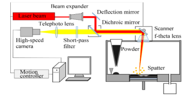
The optical path unit primarily includes a fiber laser, beam expansion and collimation lenses, mirrors and dichroic mirrors, scanning galvanometers, and F-Θ lenses, among others.
· Laser: As the core component of SLM equipment, it directly determines the overall forming quality. Fiber lasers used in SLM devices offer significant advantages, such as high conversion efficiency, reliable performance, long service life, and beam modes close to the fundamental mode.
· Beam Expansion and Collimation Lenses: These lenses expand the beam diameter, reduce beam divergence, and minimize energy loss.
· Mirrors and Dichroic Mirrors: They guide the direction of the optical path and enable beam combining.
· Scanning Galvanometers and F-Θ Lenses: These are motor-driven components controlled by a computer, designed to precisely position the laser spot at any location on the processing surface. Specialized flat-field F-Θ lenses are typically used to prevent distortion in the scanning galvanometer unit, ensuring consistent focusing characteristics of the laser spot within the scanning range.
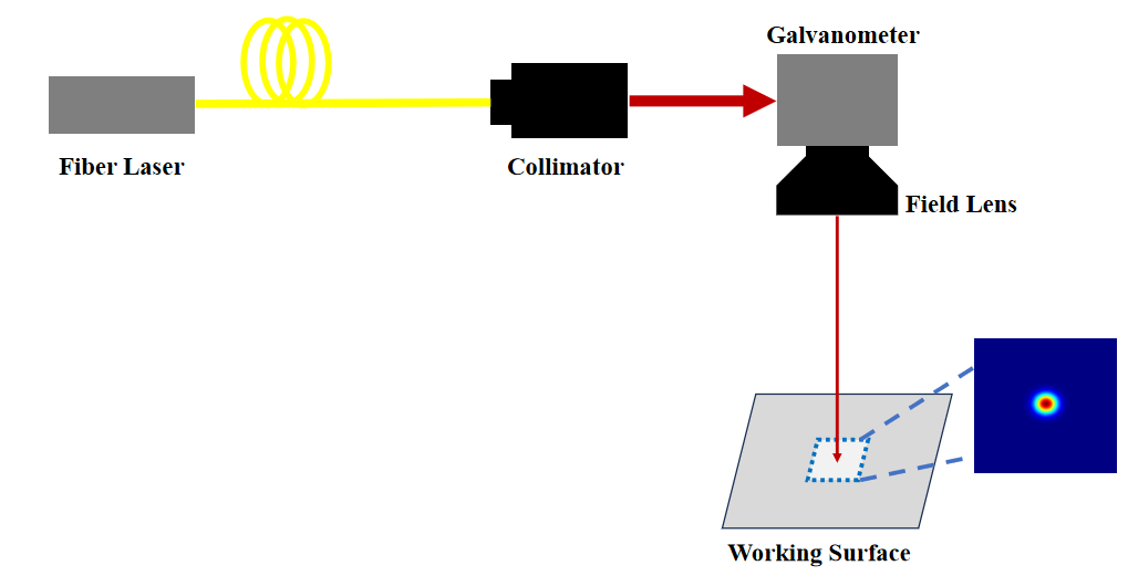
Basic optical path for SLM
Incorporating beam shaping modules into the fundamental optical path can effectively improve or address critical challenges in SLM 3D printing. These challenges include processing efficiency, spatter during fabrication, high-resolution processing requirements (as illustrated in SLM Optimized Optical Path Diagram 1), and warping issues induced by temperature gradients (as shown in SLM Optimized Optical Path Diagram 2).
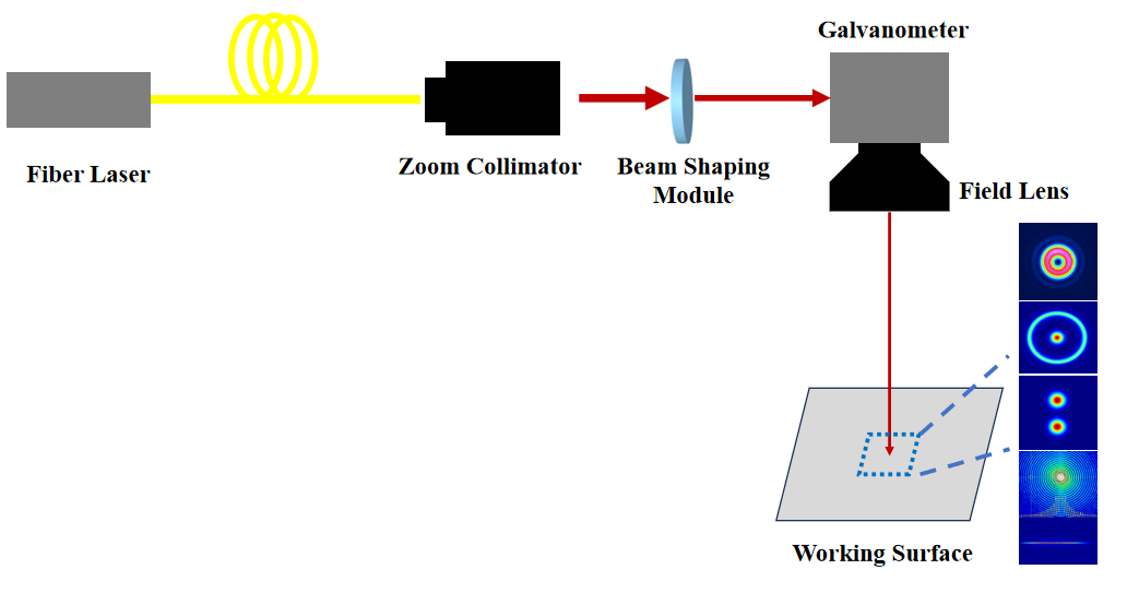
SLM Optimized Optical Path 1
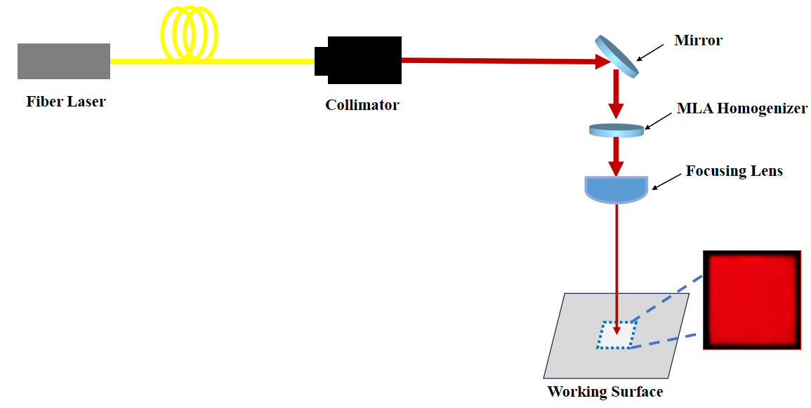
SLM Optimized Optical Path 2
To meet the diverse processing requirements of 3D printing across industries such as aerospace, medical, and automotive, LBTEK offers a range of beam shaping solutions. These include beam splitting, zoom collimators, dot/ring diffractive optical elements (DOEs), Bessel beam generators, and homogenizers. These solutions are applied in the Selective Laser Melting (SLM) process—a key technique within Laser Powder Bed Fusion (LPBF)—to address challenges such as processing efficiency, dimensional variability during fabrication, spatter during processing, the need for higher-resolution fabrication, and warping caused by temperature gradients.In addition, LBTEK designs and develops complementary optical components and related mechanical parts, including beam expanders, fixed-focus collimators, zoom collimators, field lenses, mirrors, lenses, annular DOEs, axicons, waveplates, and more. These components work together to maximize the advantages that shaped laser beams bring to laser-based manufacturing processes.
|
SLM Process Issues Requiring Improvement or Resolution |
Advantages of Beam Shaping Modules |
|
|
Processing Efficiency Issues |
· Annular or Dot-Ring DOE (or Dot-Ring Continuously Adjustable Module): · Polarization Grating or Beam-Splitting DOE: |
Collimation and Beam Expansion Module (motorized design optional) / Annular or Dot-Ring DOE / Polarization Grating or Beam-Splitting DOE / Dot-Ring Spot Continuously Adjustable Electro-Switching Device (motorized) / Field Lens (customizable based on beam shaping effects) |
|
Issue of Dimensional Variation During Processing |
A zoom collimator can adjust the diameter and divergence angle of the incident beam spot, thereby modifying the size of the focused spot and enabling precise control over the processing fineness of the product. |
Zoom Collimator / Field Lens |
|
Issue of Spatter During Processing |
Processing with a Gaussian beam spot leads to "unstable melt pool behavior," resulting in significant temperature gradients and complex melt pool instabilities at the interaction point between the laser and metal powder. This generates intense vaporization and forms a deep cavity, known as a keyhole, within the metal substrate during the build process. The keyhole can produce bubbles within the melt pool, leading to porosity and spatter effects. Compared to Gaussian beams, annular or dot-ring beam spots (or dot-ring continuously adjustable modules) and homogenizing DOEs offer a more uniform power density distribution, reducing temperature gradients and mitigating complex melt pool instabilities. |
Collimation and Beam Expansion Module (motorized design optional) / Annular or Dot-Ring DOE / Homogenizing DOE / Dot-Ring Continuously Adjustable Module (motorized) / Field Lens (customizable based on beam shaping effects) |
|
Higher-Resolution Processing |
In applications such as 3C electronics and shoe mold industries, small beam spots are required for high-resolution processing, while also necessitating a relatively large processing area. Compared to Gaussian beams, Bessel beams offer a longer solidification time for the melt pool, reduced powder spatter, lower porosity, an extended depth of focus, a smaller beam spot size, and higher densification. |
Collimation and Beam Expansion Module (motorized design optional) / Bessel Beam Processing Head / Field Lens |
|
Warping Issues Caused by Temperature Gradients |
During large-scale processing, temperature differences can lead to warping. 3D printing is typically conducted in a high-temperature, constant-temperature chamber. Heating within the chamber improves interlayer bonding and prevents warping, eliminating the need for separate tempering or annealing equipment. Post-processing can also be completed within the heated chamber. |
Collimation and Beam Expansion Module (motorized design optional) / Large-Area Homogenizing DOE / Focusing Module / Mirrors |
Email: support@lbtek.com
Tel: 400-060-6986 (Mon-Sun 9:00-18:00)
 WeChat
 TikTok
 Zhihu
Zhihu Bilibili